HiL: saving millions of kilometres every year
HiL testing involves connecting a system under development, such as electronic control for a vehicle or an industrial control system, to a real-time simulator.
The simulator replicates the behavior of the surrounding system and provides realistic inputs to the development system.
It enables testing in a controlled and repeatable environment, reproducing complex scenarios and operating conditions challenging to achieve in real-world tests.
In addition, it allows to minimize the need for expensive hardware prototypes to test software, allowing the identification and resolution of issues during the development phase.
HIL testing has become a crucial element in the development of complex systems, providing a more efficient and reliable approach to verifying the functionality and performance of embedded systems.
The aim of this first activity was to calibrate the bench at best.
Then, starting from this calibration of the EPSiL bench, a new steering rack has been developed and fine-tuned.
The calibration was performed using numerical evaluation and the human perception of a real professional driver.
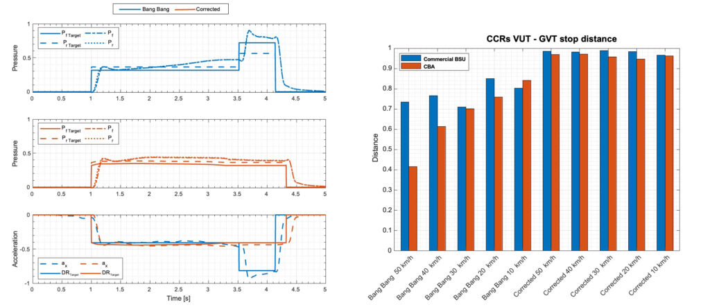
The aim of the second study was to model and test an innovative AEB control logic that will increase system reliability by compensating for the non-immediate response of brake system to brake requests.
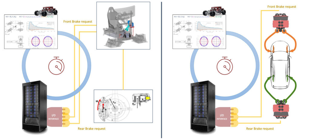
The effectiveness of the control logic has been tested on two different braking system:
1. Two CBAs ,installed on an experimental vehicle, were directly integrated into the simulation loop
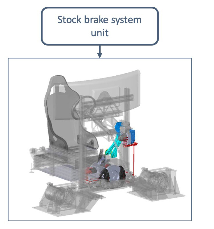
2. A stock brake system unit integrated into the static simulator
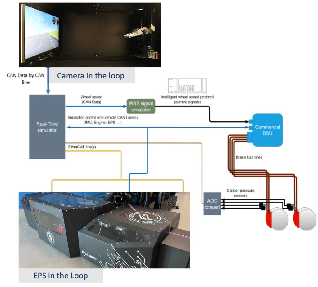
Hardware in the loop technique has been fundamental to reproduce as accurately as possible the response of the braking system to AEB triggering.
The developed controller demonstrates high reliability as it guarantees the same performance acting on two different brake systems without the need of tuning activities.
Physical validation at component and system levels
Fault injection at SW and HW levels
Automated or human-driven tests
Systems calibration in repeatable conditions

Case study: advanced HiL station for testing production grade components
Development of an Angle-Driven 2 DOF steering system model specific for real-time applications
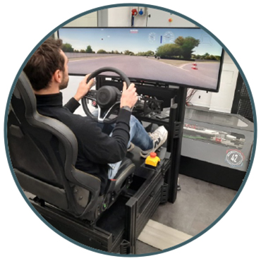
Complete chain in the Driving Simulator Loop
Steering System in the Loop, including:
- Steering assist
- Capacitive steering wheel
- …
Braking System in the Loop, including:
- ABS
- ESC
- …
Camera in the Loop
Expandable solution:
- Radar in the Loop
- Multiple cameras
- …
Possible testing activities
Steering System in the Loop, including:
- Functional validation
- FUSA
- SOTIF
- ADAS
- …
Case study: EPS control logic calibration on EPSiL
Workflow

Calibration of the new EPS

Recap of the activity
The kinematic chain, from suspension tie rod to steering wheel, is successfully replicated on our steering bench.
The simulator can hence be used for the vast majority of the new component development process.
Advantages
- Strong reduction in development time
- Sensible cost reduction
- Driving simulator experience useful for virtual vehicle development

Reference
A Virtual Development Approach Using Advanced HiL Steering Bench – Talarico, Enrico Maria, et al. 12th International Munich Chassis Symposium 2021: chassis. tech plus. Berlin, Heidelberg: Springer Berlin Heidelberg, 2022.
Case study: LCA validation
Aim
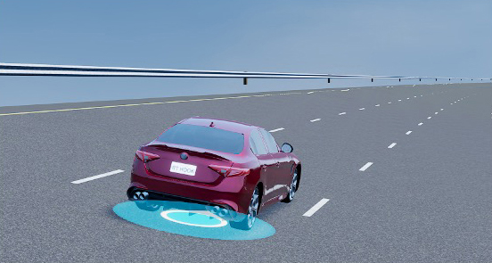
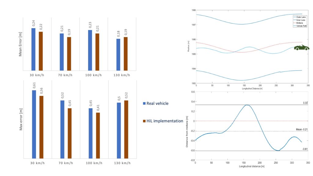
Test Lane Centering Assist system in both physical and virtual test track with HiL benches
Method
- LCA scenario definition
- Physical Testing
- Virtual Testing
- Data Analisys
Virtual test track
- Model derived from point cloud survey
- X-Y point cloud precision <5mm
- Z point cloud precision <2cm

Reference
Tool and Methodology Development for LCA Hardware in the Loop Testing – Alfatti, F., Lelli, L., Annicchiarico, C., Capitani, R. (2024). In: Pfeffer, P. (eds) 13th International Munich Chassis Symposium 2022. IMCS 2022. Proceedings. Springer Vieweg, Berlin, Heidelberg.
Vehicle and on board testing equipment
- Sedan car equipped with ADAS system
- IMU platform with differential GPS
- CAN Logger

Virtual testing
- EPSiL Test bench
- CamiL test bench
- Same test both in real and virtual scenario
Case study: AEB controller
Aim
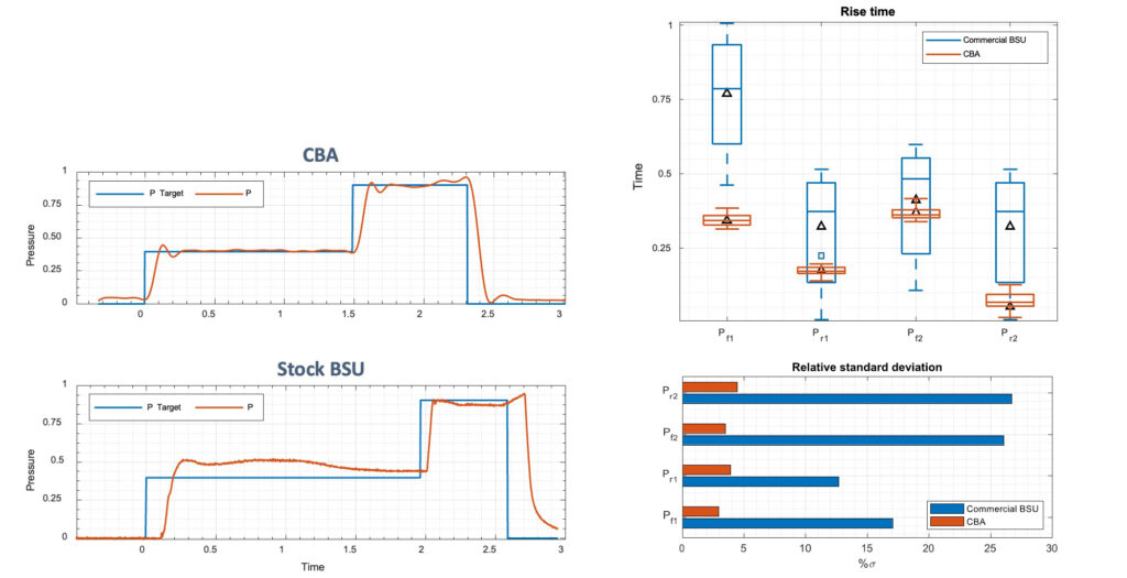
Development of an AEB controller, focused on the compensation of the delay in pressure build-up introduced by brake plant response
Brake system independent control logic
Method
Stock brakes system integrated into simulation loop
CBA and whole vehicle brake plant integrated into simulation loop
Results
Adaptable brake request controller based on vehicle status
- Brake system response compensation
High reliable controller
- No tuning activities needed

Rise time comparison between CBA and Commercial BSU
- Step response
- Pre-conditioned step response
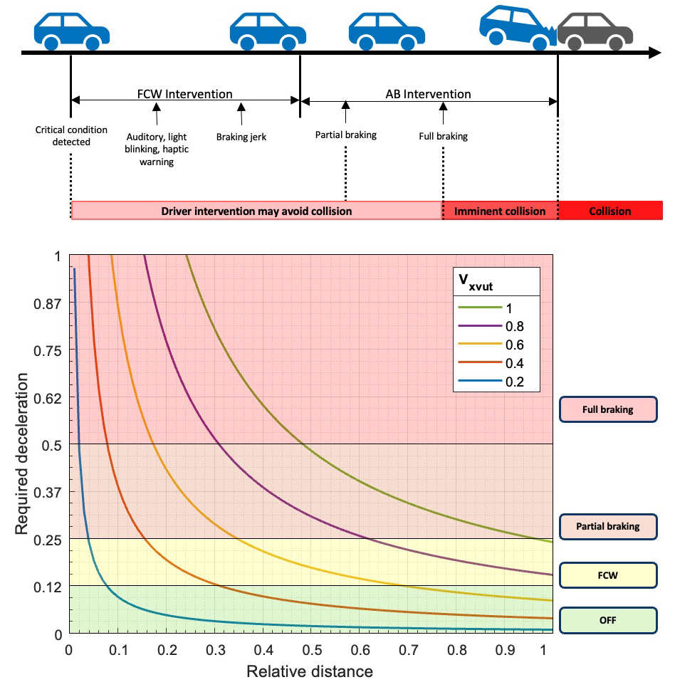
Deceleration based controller
Three state machine status
- Forward collision warning
- Partial braking
- Full braking
Adaptable brake request based on vehicle status
- Brake system response compensation
Tested on 3 different EuroNCAP rear-end collision scenario
- CCRs Car to Car Rear-end collision stationary
- CCRm Car to Car Rear-end collision moving
- CCRb Car to Car Rear-end collision braking

